
Sent via BlackBerry by AT&T
Thursday, December 30, 2010
Killer "Rocket Fuel" bladder tubes
Sent via BlackBerry by AT&T
Thursday, December 23, 2010
Leading Edge Graphix
As a spectator goes there only a few things that set the planes apart from each other, they are going to see obvious geometry differences and any tape and tail covering colors from plane to plane but that is about it. When I was looking to start building my own planes one of the aspects that was very intriguing was to find a way to set them apart in a way that the general public could see. After some various ideas like painting the wood, stenciling the covering, creative taping, and a few others that aren’t worth mentioning I found a way to print right on the LE paper itself. The printed graphics offer some really neat advantages. First and foremost great looks, with the help of a graphics program the sky is the limit, colors, text, and artwork can all be printed right to the paper. Secondly the weight added for this artwork is almost zero which is a really big deal considering that it is going to get wrapped around the LE.


Then turn off the layer with the layout lines leaving just some reference marks so you know where to cut the paper.


First create a basic layout of the paper. You can see the basic layout of the muffler area, “back” of the LE where each rib will go, top, and bottom. (My seam is on the bottom just behind the LE spar not on the “back” where the ribs are like most models)

Work up some graphics in the areas that you want using the reference lines to make sure everything fits. I like to split the screen so I can see the inboard and outboard graphics in the same window to make sure they look good together. You can see in the screen shot the active view is the outboard and under it is the inboard. This takes quite a bit of time even if you actually know what you want it to look like before you start. I am learning the software and developing the design all at the same time. As I learn new technics and get new ideas the designs evolve. Actually I can’t remember if I have done 2 sets of planes the same since I started.

Then turn off the layer with the layout lines leaving just some reference marks so you know where to cut the paper.

A couple of things to keep in mind and they will all be printer specific: you have to be able to tell the printer that you want to print on a custom paper size (in my case I use 23x8.5), the paper I use will not feed properly on its own and must be glued (dust 3M77 on a reg piece of printer paper) or taped (huge pain) to the LE paper, the ink is water soluble ( I used water and white glue for gluing it to the foam).
With some experimenting and effort you can create a unique LE. Here are a few that I have come up with.


It is hard to see in the photo but the base color has a fake wood grain, neat effect.


This is some of the new top secret stuff I have been working on this winter, do you see the bladder tube?

eles1
Sunday, December 19, 2010
Check out the new Allen DeVeusky model

eles1
Sent via BlackBerry by AT&T
Saturday, December 18, 2010

Saturday, December 11, 2010

2011 test plane RTF

Here are a few things I know for sure:
1. The drag on the lines goes up when the speed goes up/down when the speed goes down.
2. In maneuvers the speed goes down, sometimes a lot (40mph - yes you maybe going 105 in the flats but not in the turns!)
3. There used to be a formula on the www to calculate the LO position. I am sure it was based on an article published in the 50s-60s.
4. I really want to know where these should be for one simple reason- I can build my planes how ever I want and I want the BC and LO in the best possible position.
So I built a plane with an adjustable BC. In the forwards most position the BC axle is touching the back edge of the spar which puts it right on the CG of this plane, and then it can go back up to 3.75" aft. The LO positions are every 3/8" from the back edge of the spar back 3 inches.
With the externally mounted BC this is also an opportunity to try different LO line spacing and push rod throws on the BC.
Let us know what your ideas and predictions are in the comment section below.
Sent via BlackBerry by AT&T
2 builders with finished planes now!!

Eles1
Sent via BlackBerry by AT&T
Friday, December 10, 2010

Reports coming in from builders
Howard Williams and Kevin Herbstreit are cranking out Streamer Shuttles of their own as we speak.
Howard was the first one to complete a SS and get it in the air. Here is a quote from his email "The heavy SS flies fantastic. The larger bellcrank makes it easier to trim, in fact, no trimming was necessary. A slight warp to remove and that’s it – Perfect!" Howard has reported a second SS is RTF this weekend at an amazing 229g! That is the lightest SS ever! I cant wait to hear his report on that one.

Howard was the first one to complete a SS and get it in the air. Here is a quote from his email "The heavy SS flies fantastic. The larger bellcrank makes it easier to trim, in fact, no trimming was necessary. A slight warp to remove and that’s it – Perfect!" Howard has reported a second SS is RTF this weekend at an amazing 229g! That is the lightest SS ever! I cant wait to hear his report on that one.
Kevin is covering the first of his SSs tonight with hopes that he will be up and ready to fly early Saturday. Kevin has David Owens at his house helping with the project so I am confident they will have it ready to go.

eles1
Monday, December 6, 2010
Bell Cranks
I flew the new bellcranks over the weekend and they work like a charm. I really didn't expect that they wouldn't but you never now sometimes.
eles1

eles1

Thursday, December 2, 2010
The Hunt for Domestic Covering
This seems to be one of the most challenging areas of the building process, finding a good source for covering in the US. I have looked high and low all over the net and have yet to find a source for the "right stuff" and here is what I have learned:
-The covering that works the way I want comes from Eastern Europe and is of course metric; .03mm or 30 microns thick. Domestic covering is sold as 1 mil or .001 (30 microns is .00118"). The problem with 1mil film here is that it is more than likely actually 92 gauge or .00092."
-The film is often referred to as "Mylar" which is like referring to cola as Coke. The film is a biaxially oriented polyester film or PET film. There are thousands of PET films and other types that look just like them on the market and they are all different. If you add in that they can be treated/coated to have different properties finding the right one is a long shot.
- Being small fish we have to find a retailler that has the right film for sale that we can use. I have been told that the Euro covering is used as book covers, "Mylar" is widely used in the archival industry to preserve documents, art suppliers often list film, etc. I have yet to nail down the "right stuff" with this trial and error shopping. The challenges have been super high minimum orders, wrong sizes, and lack of detail about the film.
Do you know where we can get "the right stuff?" Post up some comments below.
eles1
Getting organized...
I am still working on the blog site to make it as useful to anyone building F2D planes... I added a page with the instructions so you don't have to hunt through the archive to find them.
eles1
eles1
Tuesday, November 30, 2010
Kit Instructions
Streamer Shuttle
First you will need to complete each of the 3 main sub assemblies: the leading edge, the center section, and the trailing edge/tips.
For the center section simply apply a small amount of glue (I like white Gorilla glue) to the motor mount doublers, put one on either side of the center rib. Put some glue on the small rectangular “key” and press it in the slot and apply a clamp to hold it while the glue dries. At this point I would suggest figuring out what you are going to do for the bell crank and lead outs. I salvage them off old planes most of the time but I have cut a few from .062” aluminum too. The four holes around the bell crank area are for landing gear straps (Sig part number SIGS H523) to hold a piece of 1/8” brass tubing for the axle. Depending on what you do for the bell crank you will also need a push rod stop to keep from having too much travel. I like to have the lead outs soldered to the bell crank and have it mounted before I glue the center section to the LE.

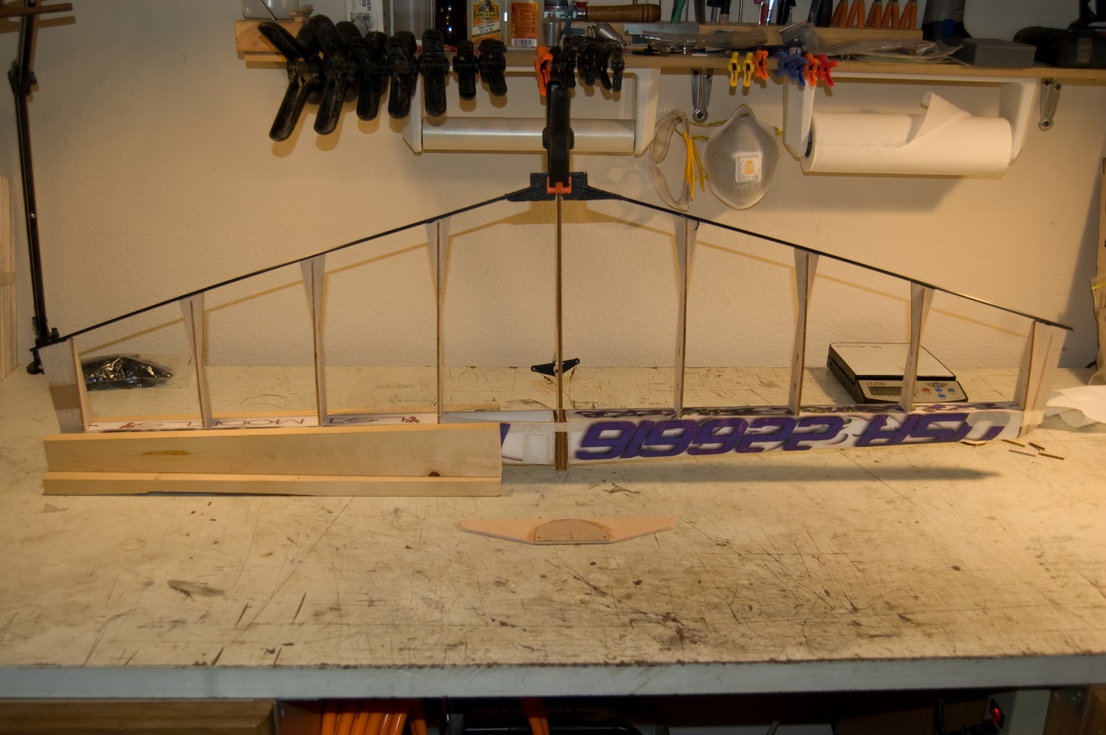
The LE assembly builds flat on the bench; the first LE you build will help you build the simple jig for the rest. To start draw a straight line on the bench longer that the LE when it’s full assembled. Glue the 3 spars and one false rib to a foam LE piece sitting flat on the bench. I use a couple of pieces of angle aluminum on either side to make sure the part is straight. After it has dried repeat the process but this time you also have to align both sides with your reference mark to make sure that the entire LE is straight. It is also very important to have the assembled center section available to make sure the spacing between the LE halves is correct. Once it is dry you can use the LE assembly to make a quick jig for the rest of the LEs. Mount some angle aluminum to a flat board and use it to assemble the rest of the LEs. Mine looks like the picture below. Next you will decide how you are going to make the muffler relief and the relief for the bladder. I Use a large “forstner” bit for the muffler area and a piece of copper wire heated with an old soldering gun to make the bladder cut out. No magic here just need to make room for things to fit. To paper the LE I like automotive masking paper, it is about the right weight and it’s cheap. Apply it with some diluted white glue. Trim and decorate as you would like.

The entire next step should be done with the parts flat on the bench to ensure that there is no twist in the TE assembly. Join the carbon tubes to the center joiner and also a tube for the elevator hinge (I like black CA or regular CA works too). Wrap the entire joiner with Kevlar cord and set with CA or apply some sort of reinforcement to the part or it will fail in a collision. Once you are satisfied that the joiner has been strengthened glue the tips on to the carbon tubes at the ends. Please reference the plans for the correct location of the tips. Next you can glue the tip ribs in place.

For the Final assembly, first dry fit all parts and make any final adjustments to them to ensure the fit you like before gluing. Apply a small amount of glue to the side of the motor mounts and where the spars will touch also, slide the center section in the LE. Next put glue on the ends of the LE where the ribs will attach and also where the TE will slide into the center section at the tail. Slide the TE into the CS and then slide the tips on and apply an 8” piece of masking tape to hold them tightly to the LE.

Next is to add the ribs. Slide the gussets onto the ribs and apply a small amount of glue to the ribs where they will touch the spars and thick CA to the back of the gussets where they will touch the carbon TE. Slide the ribs into the LE check that they are 900 to the LE and then slide the gusset out to touch the TE. Once all the glue is dry, glue the gussets to the ribs with a small amount of CA. You can also glue the tip gussets on now too.
Finish out should be straight forward from here. I like a 12g washer as tip weight. The bladder tube is one layer of patch tape wrapped sticky side out around a 1.5” pipe with strapping tape wrapped over it. Trim it to the correct length with some scissors and CA the caps on. NOTE the bladder access wood needs a spacer of about 3/16” to move it outboard to match up with the bladder tube.

I use Weldwood brand contact cement to glue the covering down. This part really throws people but keep in mind that you are going to break this plane sooner than later and you will get better with practice. Some people like to use one piece on the top and one on the bottom; I use one piece on the inboard and one on the outboard. I am not sure it really makes any difference… Seal the motor and muffler area with epoxy. The planes I build are about 240g but if you are not careful with the glue you can be 260g really fast. The plane will likely be stable to really stable because of the bigger LE so I like a fairly heavy elevator to help the balance.

*** I print the graphics right onto the paper in the ink jet. YES the ink is water soluble, so you have to be really good with the water/glue when you are gluing it to the LE foam…
*** I use 1mil “Mylar” from Europe, I know it is not the only place in the world to get it but it is the only place I know where to get it… I have been told it is type D and is used in the archival industry… If you find a source or equivalent let everyone know.
Subscribe to:
Posts (Atom)